Bigtreetech Octopus
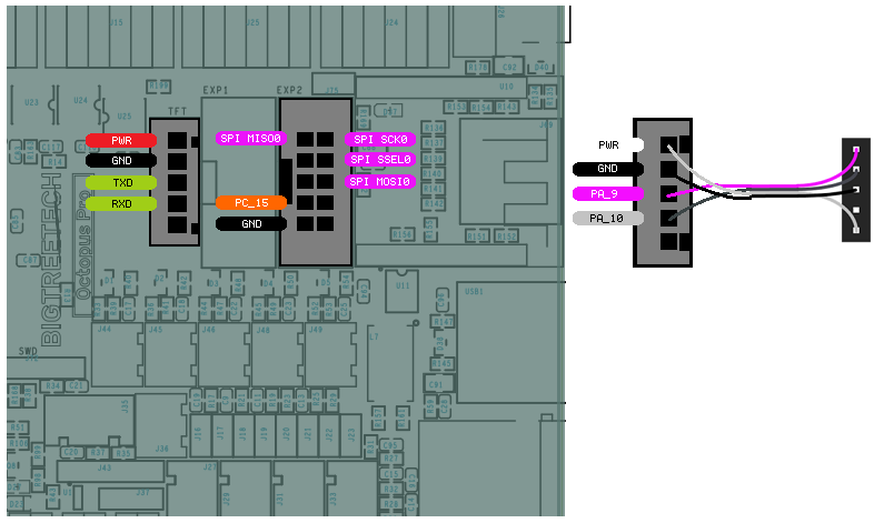
Wiring for the Octopus boards is very straight forward with all pins directly available on the EXP2 header.
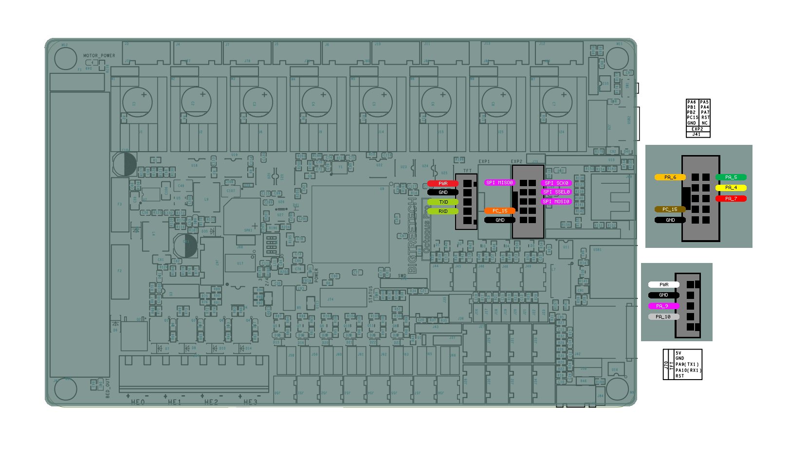
OCTOPUS PRO
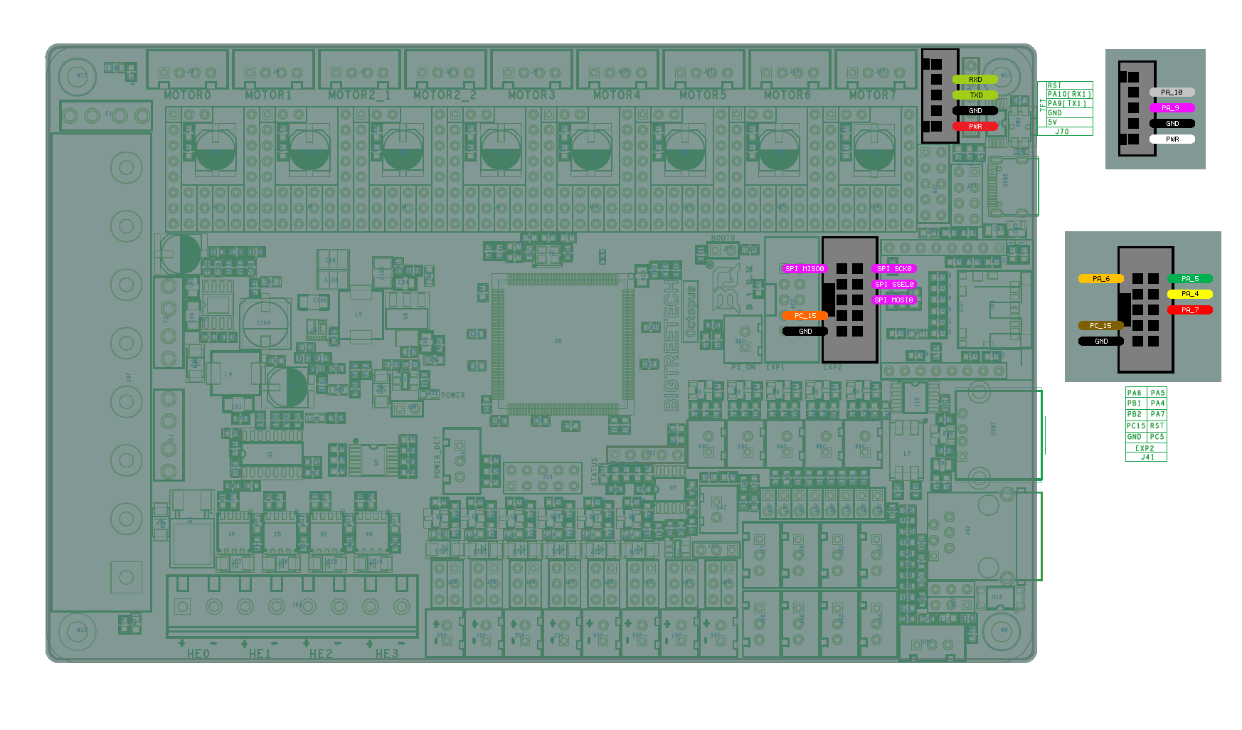
OCTOPUS v1.1
Remora Details
Firmware
The Octopus has several different versions. Currently, the only supported versions are based on the STM32F446 and STM32F429 microcontrollers. Hardware wise they are mostly the same, but they require diferent firmware. Note which board version you have and choose the matching firmware.
Firmware is loaded by putting the approiate firmware on the SD card, and the bootloader will install it from the SD card
Firmware for the STM32F429 version is STM32F429/BTT_429
Firmware for the STM32F446 version is STM32F446/BTT_446
Firmware for other versions are unavailable or untested
In your .hal file, you will need to load the Remora driver
loadrt remora-spi
Config
A sample config.txt for the BTT Octopus is located in the Remora repo under FIrmware/ConfigSamples/Octopus
The config file for the Octopus will be the same for both versions.
The config must be named config.txt and must be stored on the SD card. It must remain in the board.
Hardware Pins
Remora firmware has some features available only on specific hardware pins. These pins can vary between STM32 boards.
Available PWM Hardware pins:
PA_1 PA_2 PA_3 PA_5 PA_6 PA_7 PA_8 PA_9 PA_10 PA_11 PA_15
PB_0 PB_1 PB_3 PB_4 PB_5 PB_6 PB_7 PB_8 PB_9 PB_10 PB_11 PB_13 PB_14 PB_15
PC_6 PC_7 PC_8 PC_9
PE_5 PE_6 PE_8 PE_9 PE_10 PE_11
Available QEI Encoder Hardware pins:
PE_9
PE_11
PE_13 is used as index
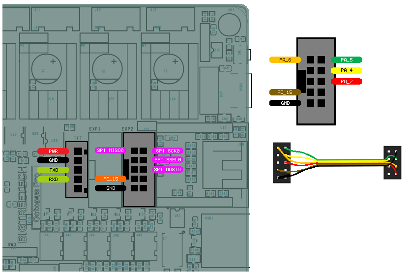
Wiring
The wiring for both versions are the same, except UART is in a different location. Wiring requires the following components:
100mm Female-Female Dupont ribbon jumper
10 way (2x5) Dupont connector
8 way (2x4) Dupont connector
The pinout for the BTT Octopus is standard for both versions and keeps the footprint of the SKR v1.4 and SKR v2.
PIN |
COLOR |
FUNCTION |
RPI PIN |
PA_7 |
RED |
SPI_MOSI |
RPI_PIN_19 |
PA_6 |
ORANGE |
SPI_MISO |
RPI_PIN_21 |
PA_5 |
GREEN |
SPI_SCK |
RPI_PIN_23 |
PA_4 |
YELLOW |
SPI_SSEL |
RPI_PIN_24 |
PC_15 |
BROWN |
PRU Reset |
RPI_PIN_22 |
PA_9 |
PURPLE |
MCU TX to RPI RXD |
RPI_PIN_10 |
PA_10 |
GREY |
MCU RX to RPI TXD |
RPI_PIN_8 |
OCTOPUS PRO
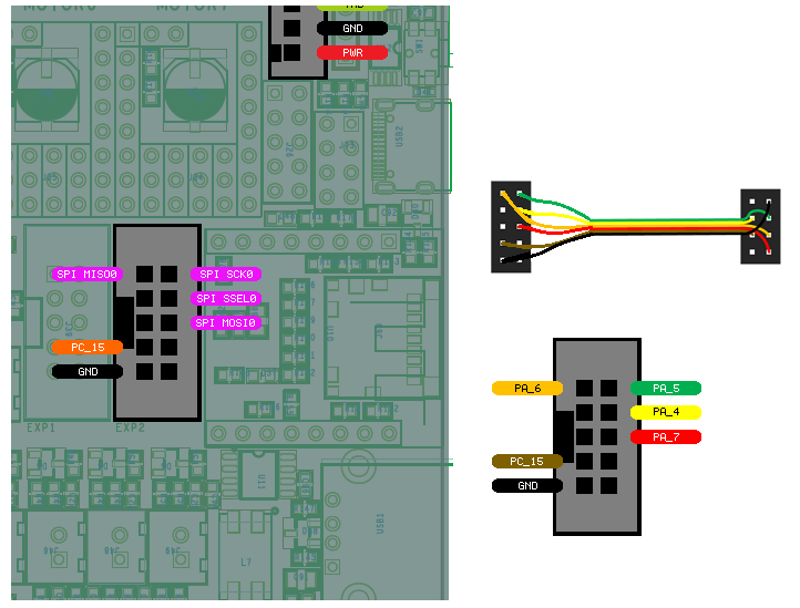
OCTOPUS v1.1
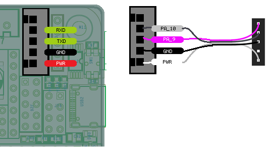
To UART from the Raspberry Pi to the Octopus the follwoing components are requried:
150mm or 200mm Female-Female Dupont ribbon jumper
5 way (1x5) Dupont connector
5 way (1x5) Dupont connector
OCTOPUS PRO
OCTOPUS v1.1
The diagram above includes the optional serial debug interface. Note that TX <-> RXD and RX <-> TXD.