Fysetc Spider
Wiring for the Spider board is very straight forward with all pins directly available on the EXP2 header.
Remora Details
Firmware
The Spider uses an STM32F446, newer versions use an STM32H723 and is not supported.
Firmware for the Fysetc Spider is located under FirmwareBin/STM32F446/SPIDER
In your .hal file, you will need to load the Remora driver
loadrt remora-spi
Config
A sample config.txt for the Fysetc Spider is located in the Remora repo under FIrmware/ConfigSamples/Fysetc_Spider
The config must be named config.txt and must be stored on the SD card. It must remain in the board.
Hardware Pins
Remora firmware has some features available only on specific hardware pins. These pins can vary between STM32 boards.
Available PWM Hardware pins:
PA_1 PA_2 PA_3 PA_5 PA_6 PA_7 PA_8 PA_9 PA_10 PA_11 PA_15
PB_0 PB_1 PB_3 PB_4 PB_5 PB_6 PB_7 PB_8 PB_9 PB_10 PB_11 PB_13 PB_14 PB_15
PC_6 PC_7 PC_8 PC_9
PE_5 PE_6 PE_8 PE_9 PE_10 PE_11
Available QEI Encoder Hardware pins:
PE_9
PE_11
PE_13 is used as index
Wiring
Wiring requires the following components:
100mm Female-Female Dupont ribbon jumper
10 way (2x5) Dupont connector
8 way (2x4) Dupont connector
The pinout for the Fysetc Spider is slightly different than other versions. Please read the pinout carefully.
PIN |
COLOR |
FUNCTION |
RPI PIN |
PA_7 |
RED |
SPI_MOSI |
RPI_PIN_19 |
PA_6 |
ORANGE |
SPI_MISO |
RPI_PIN_21 |
PA_5 |
GREEN |
SPI_SCK |
RPI_PIN_23 |
PC_6 |
YELLOW |
SPI_SSEL |
RPI_PIN_24 |
PC_7 |
BROWN |
PRU Reset |
RPI_PIN_22 |
PA_9 |
PURPLE |
MCU TX to RPI RXD |
RPI_PIN_10 |
PA_10 |
GREY |
MCU RX to RPI TXD |
RPI_PIN_8 |

SPIDER V2.2
To UART from the Raspberry Pi to the Spider the follwoing components are requried:
150mm or 200mm Female-Female Dupont ribbon jumper
5 way (1x5) Dupont connector
5 way (1x5) Dupont connector
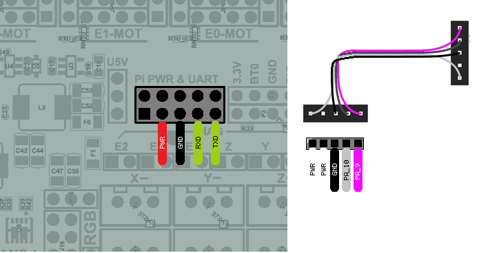
The diagram above includes the optional serial debug interface. Note that TX <-> RXD and RX <-> TXD. The standard order for serial is different with the Fysetc Spider 2.2 , so please pay close attention to the wiring.
Note: The Spider had some issues on some versions with silkscreen and PWR/GND wiring. As the PWR/GND are not needs, it is recomended to not connect those unless you are sure of the pinout.